 ®
®
Getting Started with Digital Works
Digital Works 3.05 is a circuit simulator for Microsoft Windows written by D. J. Barker at the University of Teesside. This is a free program. You may use it without any obligation, and you may give unmodified copies of it to others. Links with the ![]() symbol are Digital Works binary files.
symbol are Digital Works binary files.
![]() Download the
Digital Works installation file. This 8.2 MB zip file that can be unzipped and run without installing.
Download the
Digital Works installation file. This 8.2 MB zip file that can be unzipped and run without installing.
![]() Download the sample
circuit
Download the sample
circuit ![]() from the Designing Combinational Circuits
handout. Save the file as "sop.dwm"
in a directory you have set up for your circuit simulations.
from the Designing Combinational Circuits
handout. Save the file as "sop.dwm"
in a directory you have set up for your circuit simulations.

![]() Start Digital Works
and open file "sop.dwm" using the File menu.
Start Digital Works
and open file "sop.dwm" using the File menu.
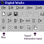
![]() Start the simulator by pressing the "run"
triangle at the left end of the third toolbar, if it isn't
already depressed. Since this is an interactive circuit, and not
one driven by a clock, nothing much will happen until you cause
it to.
Start the simulator by pressing the "run"
triangle at the left end of the third toolbar, if it isn't
already depressed. Since this is an interactive circuit, and not
one driven by a clock, nothing much will happen until you cause
it to.
![]() Select the Interactive Input, or "hand" tool by
pressing the "hand" button on the toolbar. The cursor will change
to a hand shape.
Select the Interactive Input, or "hand" tool by
pressing the "hand" button on the toolbar. The cursor will change
to a hand shape.

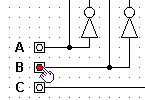
![]() Place the "hand" cursor
over one of the input buttons, A, B, or C, at the lower left of
the circuit and change its state by left-clicking. Notice how the
state of the variable and its complement change as shown by the
LED's at the top of the circuit. Observe whether the output, F,
changes state. Now run through all eight possible combinations of
A, B, and C in binary number order. (Use the truth table in the
handout to see which variables change at each step.) Check that
the output, F, reflects the value specified in the truth table.
(It does, so this circuit computes the Boolean function specified
in the truth table in the handout.)
Place the "hand" cursor
over one of the input buttons, A, B, or C, at the lower left of
the circuit and change its state by left-clicking. Notice how the
state of the variable and its complement change as shown by the
LED's at the top of the circuit. Observe whether the output, F,
changes state. Now run through all eight possible combinations of
A, B, and C in binary number order. (Use the truth table in the
handout to see which variables change at each step.) Check that
the output, F, reflects the value specified in the truth table.
(It does, so this circuit computes the Boolean function specified
in the truth table in the handout.)
![]() Now you are ready to try a circuit of your own.
Download sopframe.dwm
Now you are ready to try a circuit of your own.
Download sopframe.dwm ![]() by left-clicking the link. Open this file in Digital
Works. You will see that is is a sum-of-products circuit
design, but the AND gates aren't wired. Pick a circuit from among
the ones we drew in class; you will wire the AND gates to
simulate this circuit.
by left-clicking the link. Open this file in Digital
Works. You will see that is is a sum-of-products circuit
design, but the AND gates aren't wired. Pick a circuit from among
the ones we drew in class; you will wire the AND gates to
simulate this circuit.
![]() Select the pencil tool and place the cursor on
the topmost input of the first AND gate. When the curson is
positioned correctly, the word "Wire" will appear within the
cursor. Left-click once and release. Move the cursor to the left.
You will be dragging a wire from the AND gate. Position the
cursor over the correct vertical wire. When the word "Wire"
appears, left-click once and you will have constructed a wire to
the AND gate. Wire the remaining gate inputs. If you make a
mistake, get the pointer tool, click the incorrect wire with it,
and press the Delete key.
Select the pencil tool and place the cursor on
the topmost input of the first AND gate. When the curson is
positioned correctly, the word "Wire" will appear within the
cursor. Left-click once and release. Move the cursor to the left.
You will be dragging a wire from the AND gate. Position the
cursor over the correct vertical wire. When the word "Wire"
appears, left-click once and you will have constructed a wire to
the AND gate. Wire the remaining gate inputs. If you make a
mistake, get the pointer tool, click the incorrect wire with it,
and press the Delete key.
![]() You do not have to use all four AND gates if
the function you are simulating has fewer than four product
terms. Similarly, if you are simulating a function of two
variables, you can ignore the wiring for C and its complement.
However, the number of inputs on each AND gate must be correct;
if there is an unwired input, the AND gate will never produce
output. To change the number of inputs, use the pointer tool.
Right-click the AND gate you want to change and use the menu to
change the number of inputs.
You do not have to use all four AND gates if
the function you are simulating has fewer than four product
terms. Similarly, if you are simulating a function of two
variables, you can ignore the wiring for C and its complement.
However, the number of inputs on each AND gate must be correct;
if there is an unwired input, the AND gate will never produce
output. To change the number of inputs, use the pointer tool.
Right-click the AND gate you want to change and use the menu to
change the number of inputs.
![]() Test your circuit by running through all the
possible input values, using the truth table as a guide. Verify
that your circuit computes the function described by the truth
table.
Test your circuit by running through all the
possible input values, using the truth table as a guide. Verify
that your circuit computes the function described by the truth
table.
![]() You can clean up your circuit by using the
pointer tool and the delete key to get rid of unused
components.
You can clean up your circuit by using the
pointer tool and the delete key to get rid of unused
components.
![]() Now try simulating one of the multi-level
circuits from the text. Start with a blank workspace and arrange
gates, inputs, and LEDs by selecting them from the middle toolbar
and left-clicking to place them in the workspace. Wire your
circuit with the pencil tool and test it by cycling through all
values of the inputs.
Now try simulating one of the multi-level
circuits from the text. Start with a blank workspace and arrange
gates, inputs, and LEDs by selecting them from the middle toolbar
and left-clicking to place them in the workspace. Wire your
circuit with the pencil tool and test it by cycling through all
values of the inputs.
You can find more sample circuits here: index.html
Copyright © by Bob Brown. Some rights reserved.
This work is licensed under a Creative Commons Attribution-NonCommercial-ShareAlike 4.0 International License.
Last updated: 2023-02-06 19:08